U NUT
1. Regional Industry Context — Middle East Engineering Environment

1.1 Role of U Nuts in GCC Industrial Construction
Across Gulf Cooperation Council (GCC) projects, mechanical fastening systems are selected based on installation speed, inspection accessibility, and lifecycle maintainability rather than simple initial cost.
The U Nut functions as a non-weld, removable threaded attachment method extensively applied where sheet metal structures, equipment panels, and modular assemblies require repeatable fastening without permanent structural modification.
Typical project environments include:
- Oil & gas processing facilities
- Petrochemical plants
- Electrical control panel fabrication
- Instrumentation junction boxes
- HVAC ducting assemblies
- Modular skid packages
- Railway & metro infrastructure
- Telecom shelters
- Solar energy mounting systems
- Desalination and water treatment plants
- Power generation facilities
In these environments, mechanical attachment must comply with EPC contractor installation methodology, third-party inspection acceptance, and maintenance accessibility requirements.
1.2 GCC Construction Philosophy — Preference for Weld-Free Fastening
Large Middle East EPC projects increasingly minimize on-site welding for secondary attachments due to:
1. Hot Work Restrictions
- Refineries and gas facilities impose strict hot work permits.
- Welding introduces fire risk during brownfield upgrades.
- Cold fastening solutions reduce operational disruption.
2. Construction Schedule Compression
- Mega projects require rapid parallel assembly.
- Clip-on fastening eliminates tapping, drilling, or welding stages.
3. Labor Optimization
- Skilled welding resources are limited.
- Mechanical clip fastening enables semi-skilled installation.
4. Quality Repeatability
- Factory-produced threaded engagement offers consistent performance.
- Eliminates field tapping variability.
5. Maintenance Accessibility
- Components removable without panel damage.
- Enables inspection access to instrumentation and cable routing systems.
1.3 Environmental Operating Conditions in GCC Projects
Fastening systems installed in Middle Eastern infrastructure must withstand severe environmental stresses.
Sand and Dust Intrusion
Desert environments expose equipment to continuous airborne particulates. U Nuts permit removable covers and service panels allowing periodic cleaning without destructive removal.
Thermal Expansion Cycles
Typical temperature exposure:
- Ambient daytime: 45–60°C
- Surface temperatures: exceeding 80°C
Spring steel retention compensates for differential expansion between:
- Sheet metal panels
- Structural frames
- Equipment housings
Coastal Humidity & Offshore Salt Exposure
Facilities near coastlines or offshore platforms experience accelerated corrosion due to chloride exposure. Proper material and coating selection becomes critical.
High Vibration Environments
Common vibration sources:
- Compressors
- Pumps
- HVAC blowers
- Rail systems
- Generator packages
Elastic retention force of U Nuts provides resistance against loosening compared with rigid threaded inserts.
1.4 High-Speed Assembly Requirements
GCC projects operate under aggressive commissioning timelines. U Nuts support:
- One-side installation access
- Pre-positioned captive threads
- Rapid enclosure assembly
- Modular equipment integration
Assembly time reduction directly impacts project cost control and schedule adherence.
2. Technical Definition of U Nut
2.1 Engineering Definition
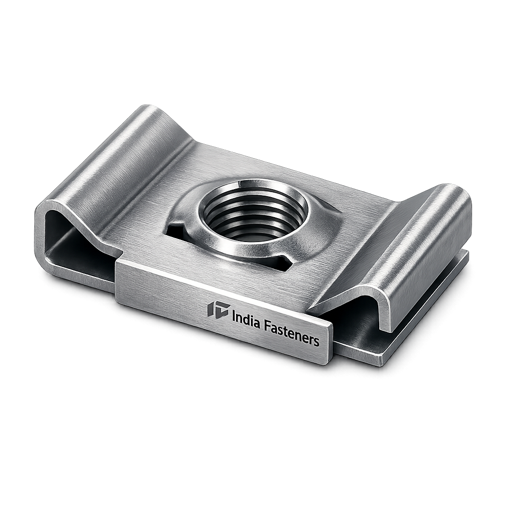
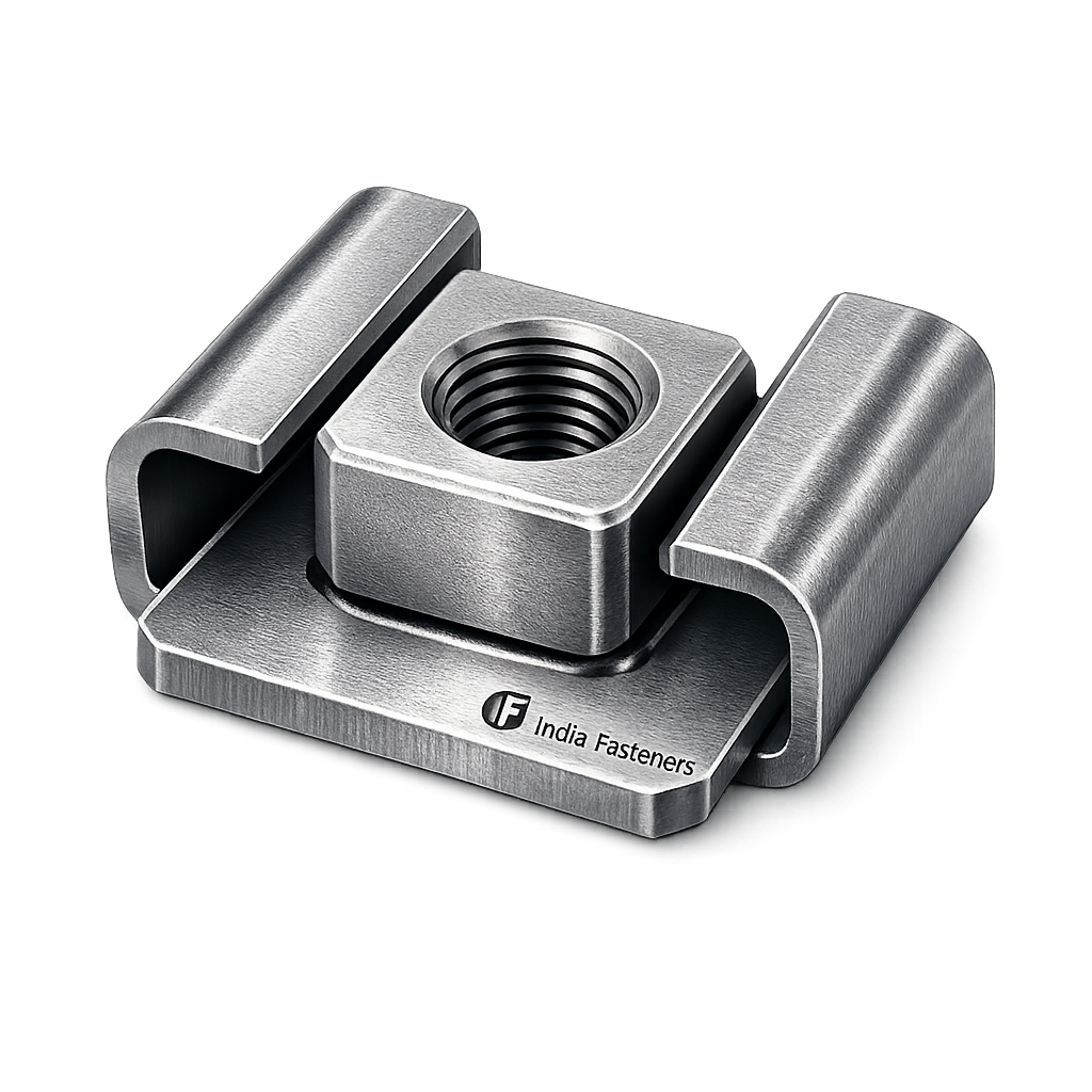
A U Nut is a:
Spring steel clip-type threaded fastener designed to attach onto sheet metal edges or pre-punched panels, providing a self-retaining floating threaded connection without welding, tapping, or rivet installation.
It functions as a removable captive nut system.
2.2 Functional Characteristics
Key mechanical characteristics include:
- Elastic spring legs providing retention force
- Threaded barrel or formed thread section
- Floating alignment capability
- Edge-mount installation
- Reusable threaded engagement
The fastener converts a plain sheet edge into a threaded mounting point.
2.3 Functional Principle
Step-wise operation:
- U Nut slides onto panel edge.
- Spring tension clamps onto sheet metal.
- Thread aligns with installation hole.
- Bolt insertion creates clamp load.
- Load transfers through clip body into panel structure.
No permanent deformation of parent material is required.
2.4 Terminology Used in Industry
Multiple industry names exist depending on application sector:
| Term | Usage Context |
|---|---|
| U Nut | General industrial terminology |
| speed nut | High-speed assembly applications |
| clip nut | Panel mounting terminology |
| J Nut | Offset leg configuration variant |
| Panel Nut | Electrical enclosure industry |
| Self-Retaining Fastener | EPC mechanical documentation |
Terminology differences relate primarily to geometry rather than operating principle.
2.5 Differences Between Related Fastener Types
- Edge mounted
- Spring retained
- Floating thread alignment
J Nut
- Single-leg design
- Used where backside clearance limited
- Generic category covering multiple clip styles
Speed Nut
- Assembly efficiency emphasis
3. Mechanical Fastening Theory & Load Behavior
3.1 Clamp Load Generation
Primary function of threaded fastening is clamp force creation.
Clamp force equation:
![\[F = \frac{T}{K \times D}\]](https://indiafastners.com/wp-content/ql-cache/quicklatex.com-1d526bf32831a128706e0d44343eae7e_l3.png "Rendered by QuickLaTeX.com")
Where:
- F = Clamp force (N)
- T = Applied torque (Nm)
- K = Torque coefficient
- D = Nominal bolt diameter (m)
U Nuts transfer clamp load through elastic clip legs rather than welded base material.
3.2 Thread Engagement Mechanics
Effective load transfer depends on:
- Thread engagement length
- Material hardness
- Bolt strength class
- Clip deformation resistance
Thread shear area:
![\[A_s = \pi \times d_m \times L_e\]](https://indiafastners.com/wp-content/ql-cache/quicklatex.com-621fc85390c0812cd266d202d4b9ed6e_l3.png "Rendered by QuickLaTeX.com")
Where:
 = mean thread diameter
 = engagement length
3.3 Sheet Metal Interaction
U Nuts are engineered to avoid sheet deformation.
Design considerations:
- Panel thickness compatibility
- Edge distance control
- Load spreading across clip surface
Excessive torque may cause:
- Panel distortion
- Thread stripping
- Spring relaxation
3.4 Pull-Out Resistance
Pull-out resistance depends on:
- Spring leg force
- Panel thickness
- Friction coefficient
- Coating condition
Unlike rivet nuts, pull-out failure typically occurs after bolt removal rather than catastrophic tearing.
3.5 Shear Load Transfer
Shear loads are transferred via:
- Bolt shank
- Clip contact area
- Panel bearing surface
U Nuts are generally selected for:
- Moderate structural loads
- Equipment covers
- Mounting brackets
- Cable management supports
3.6 Vibration Resistance Mechanism
Elastic preload offers resistance against loosening through:
- Continuous spring tension
- Micro-movement absorption
- Reduced preload loss
Desert equipment exposed to cyclic vibration benefits from flexible retention rather than rigid welding.
3.7 Torque–Tension Relationship
Torque converts into axial tension.
Approximate relationship:
![\[T = K \times F \times D\]](https://indiafastners.com/wp-content/ql-cache/quicklatex.com-ce1763d0c365717f9544d872e010b394_l3.png "Rendered by QuickLaTeX.com")
Engineering practice in GCC EPC projects requires torque control procedures documented within installation manuals.
3.8 Strip Torque Consideration
Strip torque occurs when thread shear strength is exceeded.
Safety margin commonly applied:
![\[T_{installation} = 75\% \times T_{strip}\]](https://indiafastners.com/wp-content/ql-cache/quicklatex.com-e36e4f1bc8601ea533f3c126573936f2_l3.png "Rendered by QuickLaTeX.com")
This ensures repeatable assembly without thread damage.
3.9 Safety Factor Philosophy in GCC EPC Mechanical Assemblies
Consultant-approved fastening design typically applies:
- Safety Factor: 2.0–3.0 for static loads
- Higher factors for vibration environments
- Corrosion allowance in material selection
- Maintenance accessibility consideration
U Nuts are therefore applied mainly in secondary structural attachments rather than primary load-bearing structures.
4. Comparison with Alternative Fastening Methods
4.1 U Nut vs Weld Nut
| Parameter | U Nut | Weld Nut |
|---|---|---|
| Installation | Cold assembly | Requires welding |
| Inspection | Visual | NDT sometimes required |
| Heat impact | None | Heat affected zone |
| Replacement | Easy | Permanent |
| Corrosion Risk | Lower | Weld area vulnerable |
4.2 U Nut vs Rivet Nut
| Parameter | U Nut | Rivet Nut |
|---|---|---|
| Tool Requirement | None | Installation tool required |
| Installation Time | Very fast | Moderate |
| Removal | Non-destructive | Permanent deformation |
| Reusability | High | Limited |
4.3 U Nut vs cage nut
| Parameter | U Nut | Cage Nut |
|---|---|---|
| Mounting | Edge clip | Square hole mount |
| Typical Use | Panels & ducts | Server racks |
| Installation Speed | Faster | Moderate |
4.4 U Nut vs Tapped Hole
| Parameter | U Nut | Tapped Hole |
|---|---|---|
| Thin Sheet Capability | Excellent | Limited |
| Repairability | Replaceable | Requires re-tapping |
| Alignment | Floating | Fixed |
4.5 U Nut vs Self-Tapping Screw
Parameter | U Nut | Self-Tapping Screw |
|---|---|---|
| Reuse Capability | High | Low |
| Thread Integrity | Controlled | Progressive damage |
| Maintenance Access | Excellent | Degrades over cycles |
5. Applicable Standards — Alignment with GCC EPC Requirements
Industrial fastening components supplied to Middle East EPC projects are evaluated against internationally recognized material, mechanical, and manufacturing standards. U Nuts, although classified as secondary fastening elements, remain subject to consultant scrutiny due to their widespread use across safety-critical access panels, electrical enclosures, HVAC assemblies, and instrumentation mounting systems.
Compliance verification focuses on material integrity, mechanical performance, and traceability discipline rather than product appearance.
5.1 ISO Mechanical Property Framework
ISO 898 Series — Mechanical Properties of Fasteners
While ISO 898 primarily governs bolts and screws, it establishes compatibility requirements between threaded fasteners and mating components such as U Nuts.
Relevance to U Nuts:
- Ensures thread compatibility with ISO metric bolts
- Prevents thread galling or mismatch
- Supports defined clamp load capability
- Maintains predictable torque–tension behavior
Typical EPC expectation:
- U Nuts must safely engage ISO property class bolts (e.g., 8.8, 10.9 where applicable)
- Nut material hardness must remain below bolt hardness to prevent thread seizure.
5.2 DIN Fastener References
Although no single DIN standard exclusively defines U Nuts, multiple DIN references govern dimensional and material expectations.
DIN references commonly referenced by consultants include:
- DIN 7965 — Spring steel clip fastener concepts
- DIN 6799 — Retaining and spring steel component practices
- DIN EN ISO thread tolerancing standards
These references provide:
- Spring steel behavior guidelines
- Elastic deformation requirements
- Dimensional repeatability expectations
5.3 IFI Fastener Standards
Industrial Fasteners Institute (IFI) standards are frequently referenced within multinational EPC procurement documents.
IFI relevance includes:
- Thread geometry conformity
- Material performance expectations
- Manufacturing discipline guidance
- Mechanical reliability consistency
Projects involving multinational contractors often accept IFI alignment alongside ISO/DIN compliance.
5.4 ASTM Material Specifications
U Nuts manufactured from sheet steel rely heavily on ASTM sheet material standards.
ASTM A1008
Cold-rolled carbon steel sheet.
Characteristics:
- Controlled surface finish
- Uniform thickness tolerance
- Excellent formability for spring components
Typical applications:
- Electrical panels
- Indoor industrial assemblies
ASTM A1011
Hot-rolled structural steel sheet.
Characteristics:
- Higher structural robustness
- Suitable for thicker clips
- Improved durability under heavy assembly loads
Typical applications:
- HVAC duct supports
- Mechanical equipment mounting
5.5 SAE Compatibility Considerations
SAE J429 defines bolt mechanical properties in imperial systems.
U Nuts supplied for GCC projects must maintain compatibility with:
- UNC threads
- UNF threads
- Mixed metric–imperial installations common in brownfield facilities.
5.6 RoHS and REACH Environmental Compliance
Major GCC operators increasingly require environmental compliance documentation.
Typical requirements include:
- Restriction of hazardous substances (RoHS)
- Chemical substance declaration (REACH)
- Absence of prohibited heavy metals in coatings
These requirements primarily affect:
- Zinc plating chemistry
- Passivation systems
- Surface treatments
5.7 EPC Documentation Expectations
Consultants and third-party inspectors typically request:
- Material Test Certificates (EN 10204 3.1)
- Coating compliance declaration
- Heat treatment verification records
- Dimensional inspection reports
- Batch traceability documentation
U Nuts supplied without documented manufacturing discipline are typically rejected during vendor evaluation stages.
6. Material Grades Used for U Nuts
Material selection determines performance under GCC environmental exposure and installation conditions.
6.1 Spring Steel (High Carbon Steel)
Most widely used material.
Characteristics:
- High elastic modulus
- Excellent spring memory
- Strong retention force
- Economical production capability
Typical applications:
- Electrical cabinets
- Control panels
- HVAC sheet metal assemblies
Operating temperature range:
- −40°C to +120°C (continuous)
6.2 Phosphated Carbon Steel
Carbon steel with protective phosphate conversion coating.
Advantages:
- Improved friction control
- Assembly torque stability
- Moderate corrosion resistance indoors
Used where:
- Indoor industrial environments exist
- Paint-coated assemblies provide secondary protection.
6.3 Stainless Steel 304
Selected where corrosion resistance is critical.
Characteristics:
- Non-magnetic (annealed condition)
- Excellent atmospheric corrosion resistance
- Suitable for humid coastal regions
Typical GCC usage:
- Desalination plants
- Food-grade facilities
- Electrical outdoor enclosures
Operating temperature capability:
Up to approximately 300°C intermittent exposure.
6.4 Stainless Steel 316
Enhanced corrosion-resistant alloy.
Benefits:
- Superior chloride resistance
- Offshore suitability
- Long-term durability in marine environments
Applications:
- Offshore platforms
- Coastal refineries
- Marine HVAC systems
- Water treatment plants
6.5 Alloy Spring Steel
Used in heavy-duty or vibration-critical installations.
Characteristics:
- Higher fatigue resistance
- Improved elastic recovery
- Greater load capability
Applied in:
- Rail infrastructure
- Generator enclosures
- Compressor housings
6.6 Heat-Treated Steel Variants
Heat-treated carbon steels provide:
- Increased hardness
- Higher retention force
- Improved wear resistance
Requires strict embrittlement control procedures.
7. Mandatory Material Comparison Table
| Material Grade | Yield Strength (MPa) | Hardness Range (HV) | Corrosion Resistance | Temperature Capability | Typical Middle East Application |
|---|---|---|---|---|---|
| Spring Steel | 700–1000 | 350–480 | Moderate | Up to 120°C | Panels, HVAC ducts |
| Phosphated Carbon Steel | 500–700 | 250–350 | Indoor Moderate | Up to 100°C | Indoor enclosures |
| Stainless Steel 304 | 215–505 | 150–220 | High | Up to 300°C | Coastal installations |
| Stainless Steel 316 | 205–515 | 150–220 | Very High | Up to 350°C | Offshore & desalination |
| Alloy Spring Steel | 900–1200 | 400–520 | Moderate | Up to 150°C | Rail & heavy equipment |
8. Heat Treatment & Spring Performance Control
8.1 Cold Forming Mechanics
Initial manufacturing involves:
- Progressive die stamping
- Cold deformation of steel sheet
- Controlled grain flow orientation
Cold forming increases strength through work hardening while preserving ductility.
8.2 Hardening Process
After forming, components undergo hardening through controlled heating cycles:
- Austenitizing phase
- Rapid quenching
- Martensitic transformation
Objective:
Achieve required spring hardness without brittleness.
8.3 Tempering Cycle
8.7 Hardness Verification Methods
Inspection procedures include:
- Vickers hardness testing
- Rockwell hardness verification
- Statistical batch sampling
Consultant acceptance requires documented hardness consistency.
9. Manufacturing Process Flow — Documentation-Level Control
U Nut manufacturing must follow disciplined industrial production procedures compatible with EPC vendor qualification audits.
9.1 Raw Material Receipt & Inspection
Incoming steel coils undergo:
- Chemical composition verification
- Mechanical property confirmation
- Surface defect inspection
- Thickness tolerance measurement
Material heat numbers recorded for traceability.
9.2 Material Certification Verification
Each batch linked to:
- Mill Test Certificates
- Heat identification numbers
- Compliance documentation archive
Traceability maintained throughout production.
9.3 Progressive Die Stamping
High-speed stamping operations perform:
- Blank cutting
- Profile shaping
- Thread pre-forming
- Leg geometry creation
Tooling precision directly affects retention performance.
9.4 Thread Formation
Threads produced by:
- Extrusion forming
- Tapping
- Thread rolling (depending on design)
Thread quality verified using GO/NO-GO gauges.
9.5 Spring Profile Forming
Critical manufacturing stage.
Controlled forming establishes:
- Leg tension
- Grip force
- Panel retention characteristics
Spring geometry monitored continuously.
9.6 Deburring Process
Removal of sharp edges prevents:
- Coating failure
- Installer injury
- Thread damage
Processes include tumbling or vibratory finishing.
9.7 Surface Preparation
Pre-treatment operations:
- Degreasing
- Pickling
- Cleaning
- Activation
Essential for coating adhesion.
9.8 Coating Application
Common processes:
- Zinc electroplating
- Mechanical galvanizing
- Phosphate coating
- Zinc-nickel plating
- Geomet/Dacromet systems
Coating selection aligned with project corrosion specification.
9.9 Heat Treatment Integration
Heat treatment may occur:
- Before coating (preferred for embrittlement control)
- Under monitored furnace atmosphere
Temperature profiles recorded for batch documentation.
9.10 Final Inspection
Inspection stages include:
- Dimensional verification
- Thread inspection
- Spring force testing
- Coating thickness measurement
- Visual inspection
Non-conforming batches segregated.
9.11 Batch Traceability Marking
Traceability maintained via:
- Lot numbers
- Production date coding
- Material heat references
- Inspection records
Required for EPC project documentation submission.
9.12 Tolerance Control & Dimensional Repeatability
Consultant evaluation emphasizes repeatability rather than single sample acceptance.
Critical tolerances include:
- Thread concentricity
- Clip width
- Grip range accuracy
- Alignment tolerance
Statistical Process Control (SPC) methods ensure manufacturing stability.
10. Dimensional Reference Tables — Engineering Selection Data
U Nuts are primarily selected based on panel thickness compatibility, thread size, and required clamp load capacity. EPC design engineers typically reference dimensional data during panel fabrication design, enclosure standardization, and mechanical interface reviews.
Dimensional control ensures:
- Proper spring retention
- Thread alignment accuracy
- Installation repeatability
- Prevention of panel distortion
Values below represent commonly applied industrial configurations used across GCC EPC mechanical assemblies.
10.1 Standard Metric U Nut Dimensional Reference
| Thread Size | Panel Thickness Range (mm) | Clip Width (mm) | Grip Range (mm) | Recommended Screw Size | Installation Clearance Hole (mm) |
|---|---|---|---|---|---|
| M4 | 0.6 – 1.6 | 9.0 | 1.0 | M4 Bolt | 4.5 |
| M5 | 0.8 – 2.0 | 11.0 | 1.2 | M5 Bolt | 5.5 |
| M6 | 1.0 – 2.5 | 13.5 | 1.5 | M6 Bolt | 6.6 |
| M8 | 1.5 – 3.0 | 17.0 | 2.0 | M8 Bolt | 9.0 |
| M10 | 2.0 – 4.0 | 21.0 | 2.5 | M10 Bolt | 11.0 |
10.2 UNC Thread Dimensional Reference
| Thread Size | Panel Thickness Range (in) | Clip Width (in) | Grip Range (in) | Recommended Screw | Clearance Hole (in) |
|---|---|---|---|---|---|
| #8-32 | 0.024 – 0.063 | 0.35 | 0.040 | #8 Screw | 0.173 |
| #10-24 | 0.030 – 0.075 | 0.40 | 0.050 | #10 Screw | 0.196 |
| 1/4-20 | 0.040 – 0.100 | 0.50 | 0.060 | 1/4 Bolt | 0.266 |
| 5/16-18 | 0.060 – 0.120 | 0.65 | 0.070 | 5/16 Bolt | 0.328 |
10.3 Engineering Selection Guidance
Proper sizing requires verification of:
- Sheet metal thickness tolerance
- Coating thickness addition
- Thermal expansion allowance
- Bolt engagement length ≥ 1× nominal diameter
Incorrect grip range selection leads to reduced retention force.
11. Load Capacity Table — Engineering Allowables
Load values presented are typical engineering reference ranges. Final allowable loads must always consider:
- Safety factor
- Material grade
- Coating condition
- Installation torque control
- Operating environment
11.1 Allowable Load Capacity (Spring Steel U Nuts)
| Thread Size | Tensile Allowable Load (N) | Shear Load Capacity (N) | Approx Pull-Out Resistance (N) | Recommended Torque Limit (Nm) |
|---|---|---|---|---|
| M4 | 900 | 700 | 450 | 2.5 |
| M5 | 1,500 | 1,100 | 700 | 5 |
| M6 | 2,400 | 1,800 | 1,100 | 9 |
| M8 | 4,500 | 3,200 | 2,000 | 22 |
| M10 | 7,000 | 5,000 | 3,200 | 40 |
11.2 Engineering Interpretation
Tensile Load
Represents axial clamp load before thread failure risk.
Shear Load
Represents transverse loading transferred through bolt shank and clip body.
Pull-Out Resistance
Defines resistance against clip disengagement from panel edge.
U Nuts are generally classified as secondary structural fasteners.
12. Torque Specification Chart (MANDATORY)
Torque application is critical in preventing:
- Thread stripping
- Spring relaxation
- Panel deformation
- Clamp load loss
12.1 Metric Bolt Torque Values
| Thread | Property Class | Dry Torque (Nm) | Lubricated Torque (Nm) |
|---|---|---|---|
| M4 | 8.8 | 3 | 2.2 |
| M5 | 8.8 | 6 | 4.5 |
| M6 | 8.8 | 10 | 7.5 |
| M8 | 8.8 | 25 | 18 |
| M10 | 8.8 | 50 | 37 |
12.2 UNC Bolt Torque Values
| Thread | Bolt Grade | Dry Torque (ft-lb) | Lubricated Torque (ft-lb) |
|---|---|---|---|
| #8-32 | Grade 5 | 1.7 | 1.2 |
| #10-24 | Grade 5 | 2.8 | 2.0 |
| 1/4-20 | Grade 5 | 8 | 6 |
| 5/16-18 | Grade 5 | 17 | 13 |
12.3 Torque–Tension Engineering Relationship
Approximately:
- 85–90% of applied torque is lost to friction.
- Only 10–15% converts into useful clamp force.
Variables influencing torque:
- Surface coating
- Lubrication presence
- Thread finish
- Operator installation method
EPC installations frequently require calibrated torque tools.
13. Coating & Corrosion Protection Table
Coating selection represents one of the most scrutinized areas during GCC project approval.
13.1 Comparative Coating Performance
| Coating Type | Corrosion Resistance | Marine Exposure | Desert Climate | Indoor Panels | Chemical Plants |
|---|---|---|---|---|---|
| Zinc Plated | Moderate | Limited | Acceptable | Excellent | Moderate |
| Zinc Nickel | High | Good | Excellent | Excellent | Good |
| Mechanical Galvanized | High | Good | Very Good | Good | Moderate |
| Black Phosphate | Low | Not Recommended | Indoor Only | Good | Limited |
| Geomet / Dacromet | Very High | Excellent | Excellent | Excellent | Excellent |
| Stainless Steel | Excellent | Excellent | Excellent | Excellent | Excellent |
13.2 GCC Environmental Mapping
Offshore Platforms
- Stainless Steel 316
- Zinc-Nickel
- Geomet systems
Desert Onshore Facilities
- Zinc plated with passivation
- Mechanical galvanized coatings
Electrical Indoor Installations
- Phosphated or zinc-plated carbon steel acceptable.
13.3 Coating Thickness Control
Typical inspection ranges:
- Zinc plating: 8–12 µm
- Zinc-Nickel: 12–15 µm
- Mechanical galvanizing: 25–50 µm
Coating thickness verified using magnetic measurement instruments.
14. Mechanical Property Table
Mechanical performance parameters are validated through controlled testing procedures.
| Property | Typical Range |
|---|---|
| Hardness | 350–480 HV (Spring Steel) |
| Spring Retention Force | 80–250 N depending on size |
| Clamp Load Capability | Up to 7 kN (M10 size) |
| Elastic Deflection | 0.5–2.5 mm |
| Fatigue Resistance | High under cyclic vibration |
| Operating Temperature | −40°C to +150°C typical |
14.1 Spring Retention Force
Defines ability of clip to remain positioned before bolt installation.
Critical for:
- Vertical panel installation
- Overhead assembly
- Field pre-assembly operations
14.2 Elastic Deflection Limits
Elastic behavior allows repeated installation cycles without permanent deformation.
Plastic deformation is considered failure mode.
14.3 Fatigue Resistance
Spring steel maintains performance under:
- Compressor vibration
- Rail dynamic loading
- Generator operation
- HVAC cyclic movement
15. Inspection & Quality Assurance — GCC Consultant Expectations
U Nuts supplied to Middle East EPC projects undergo verification comparable to other mechanical fasteners despite their classification as secondary components.
Inspection discipline confirms consistency rather than single-sample conformity.
15.1 Dimensional Inspection
Verification includes:
- Clip width tolerance
- Thread concentricity
- Leg spacing
- Grip range measurement
- Alignment accuracy
Measurement tools:
- Digital calipers
- Optical inspection systems
- Gauge fixtures
15.2 Thread Gauge Verification
Threads verified using:
- GO gauge acceptance
- NO-GO gauge rejection
Ensures compatibility with international bolt standards.
15.3 Hardness Testing
Performed using:
- Vickers hardness testing
- Rockwell scale verification
Purpose:
- Confirm proper heat treatment
- Avoid brittle failure
- Maintain spring elasticity
15.4 Coating Thickness Inspection
Methods include:
- Magnetic thickness gauges
- X-ray fluorescence verification (where required)
Coating uniformity prevents localized corrosion initiation.
15.5 Salt Spray Corrosion Testing
Typical verification based on:
- ASTM B117 methodology
- 72–720 hour exposure depending on specification
Used to validate coating performance prior to shipment approval.
15.6 Mechanical Load Testing
Validation may include:
- Pull-out testing
- Torque-to-failure testing
- Spring retention measurement
- Clamp load confirmation
Testing records retained for project documentation.
15.7 Batch Traceability Control
Traceability system links:
- Raw material heat number
- Production batch
- Heat treatment lot
- Coating process batch
- Final inspection record
Traceability enables investigation capability during operational service life.
15.8 EN 10204 3.1 Certification
Typical documentation package includes:
- Material chemical composition
- Mechanical property verification
- Heat treatment confirmation
- Coating compliance declaration
- Inspection authorization signature
This level of documentation aligns with GCC third-party inspection expectations.
15.9 Third-Party Inspection Interface
Inspection agencies typically review:
- Manufacturing process records
- Calibration certificates
- Inspection procedures
- Traceability documentation
- Packaging verification
Acceptance focuses on manufacturing discipline rather than visual appearance alone.
16. Industries Served — Middle East Industrial Application Focus
U Nuts are categorized as secondary mechanical fastening elements, yet their application volume across GCC projects is significant. Proper selection directly influences installation efficiency, maintenance accessibility, and long-term operational reliability.
The following sections describe engineering deployment across major regional industries.
16.1 Oil & Gas Processing Facilities
Oil & gas installations across the Middle East prioritize modular construction and maintainability. U Nuts support equipment where permanent welding is undesirable.
Typical applications include:
- Instrumentation panel mounting
- Analyzer cabinets
- Cable tray cover retention
- Junction box assemblies
- Local control stations
- Fire & gas detector housings
- Access panel fastening on skids
- Pump and compressor auxiliary covers
Engineering advantages:
- Eliminates hot work during brownfield modifications
- Allows inspection access without structural damage
- Supports fast replacement during shutdown maintenance
- Maintains fastening integrity under vibration conditions
In hydrocarbon environments, removable fastening systems reduce downtime during scheduled turnarounds.
16.2 Electrical Panel Manufacturing
Electrical enclosure manufacturers represent one of the largest industrial users of U Nuts.
Common uses:
- Door panel attachments
- Internal mounting rails
- Component brackets
- Cable management systems
- Grounding plate fixation
- Ventilation panel mounting
Panel fabrication benefits include:
- No tapping required on thin sheet metal
- Reduced fabrication time
- Uniform thread alignment across production batches
- Simplified field assembly
Floating thread capability compensates for tolerance variation between fabricated panels and structural frames.
16.3 HVAC Duct Systems
HVAC infrastructure in GCC projects operates under demanding environmental conditions.
U Nut applications include:
- Duct reinforcement brackets
- Access hatch mounting
- Inspection cover attachment
- Vibration isolator connections
- Diffuser mounting frames
Engineering relevance:
- Allows removal for cleaning operations
- Prevents duct distortion caused by self-tapping screws
- Reduces installation time on large air distribution networks
Spring retention minimizes loosening caused by fan-induced vibration.
16.4 Railway & Metro Infrastructure
Rail transport expansion throughout the Middle East requires fasteners compatible with vibration and maintenance cycles.
U Nuts are used for:
- Equipment cabinet installation
- Cable trunking covers
- Passenger information systems
- Signage panels
- Interior equipment access panels
Advantages:
- Rapid installation during track possession windows
- Replacement without structural drilling
- Reduced maintenance labor requirements
Elastic retention improves reliability under cyclic dynamic loading.
16.5 Telecommunication Installations
Telecom shelters and communication infrastructure depend on removable enclosure systems.
Applications:
- Outdoor cabinet assembly
- Rack mounting panels
- Cooling system covers
- Antenna equipment housings
- Battery compartment panels
Engineering requirement:
- Fast field serviceability
- Corrosion-resistant materials for coastal towers
- Repeatable assembly across standardized shelters
16.6 Solar Energy Mounting Systems
Renewable energy installations across Saudi Arabia, UAE, and Qatar increasingly use modular equipment enclosures.
Typical installations:
- Inverter cabinets
- Monitoring units
- Control enclosures
- Cable protection panels
U Nuts enable:
- Non-destructive assembly
- Easy component upgrade
- Maintenance access in remote desert locations
Material selection must account for UV exposure and high thermal cycling.
16.7 Water Treatment & Desalination Plants
Desalination facilities present aggressive corrosion environments.
Common U Nut usage:
- Control cabinets
- Chemical dosing systems
- Pump access covers
- Electrical housings
- Instrument enclosures
Stainless steel variants are typically specified due to chloride exposure.
16.8 MEP Contracting Projects
Mechanical, Electrical, and Plumbing contractors deploy U Nuts extensively during installation.
Applications include:
- Support bracket mounting
- Equipment access panels
- Cable tray accessories
- Fan coil unit covers
- Service hatch fastening
Installation advantages:
- Minimal tooling requirement
- Reduced installation training
- Fast corrective maintenance capability
17. Export & GCC Supply Capability
India Fasteners operates as an industrial manufacturer supplying project-based quantities aligned with EPC procurement workflows.
17.1 Regional Export Coverage
Supply capability extends to:
- Saudi Arabia
- United Arab Emirates
- Qatar
- Oman
- Kuwait
- Bahrain
Export execution aligns with EPC contractor logistics schedules and project documentation requirements.
17.2 Export Packaging Standards
Industrial packaging objectives include protection against corrosion, mechanical damage, and moisture ingress.
Typical packaging methodology:
- Batch-segregated cartons
- Moisture barrier liners
- VCI corrosion protection materials
- Heavy-duty export cartons
- Palletized shipment units
- Shrink-wrapped pallet protection
Packaging identification includes:
- Part number
- Batch number
- Quantity verification
- Manufacturing traceability reference
17.3 Moisture Protection Methods
Shipments to GCC ports experience long transit durations and temperature variation.
Protection measures:
- Desiccant inclusion
- Vapor corrosion inhibitor packaging
- Sealed inner bags
- Humidity control during container loading
Prevents early oxidation prior to site delivery.
17.4 Project Documentation Packs
Typical export documentation includes:
- Commercial invoice
- Packing list
- Certificate of origin
- EN 10204 3.1 material certificates
- Coating compliance declaration
- Inspection reports
- Batch traceability documentation
Documentation structure follows EPC vendor data book format.
17.5 Inspection Release Documentation
When third-party inspection is required, shipment release typically includes:
- Inspection release note
- Dimensional inspection summary
- Material verification approval
- Visual inspection confirmation
Inspection coordination may occur at manufacturing facility prior to dispatch.
17.6 Container Loading Methodology
Loading practices emphasize:
- Load stability
- Moisture prevention
- Carton compression avoidance
- Pallet weight distribution
- Container sealing verification
Container packing lists correspond directly with shipment traceability records.
18. Installation Engineering Guidelines
Proper installation ensures designed mechanical performance.
18.1 Clip Positioning
Correct installation requires:
- Full seating of clip against panel edge
- Alignment with clearance hole
- Absence of deformation during placement
Clips must not be forced beyond intended grip range.
18.2 Panel Thickness Compatibility
Engineers must verify:
- Sheet thickness within specified grip range
- Coating buildup consideration
- Absence of burrs on panel edge
Incorrect thickness reduces retention force.
18.3 Recommended Screw Engagement
Engineering guideline:
Minimum thread engagement ≥ nominal bolt diameter.
Example:
- M6 bolt requires ≥ 6 mm effective engagement.
18.4 Torque Application Discipline
Recommended practices:
- Use calibrated torque tools
- Avoid impact driver installation
- Apply torque progressively
- Follow project torque specification
Over-torque remains primary failure cause in clip fasteners.
18.5 Vibration Resistance Practices
Where vibration is significant:
- Use prevailing torque bolts where required
- Apply thread-locking compounds if specified
- Ensure correct spring steel hardness
- Periodically inspect high-cycle assemblies
18.6 Field Inspection Checklist
Installers or inspectors typically verify:
- Clip fully seated
- Thread alignment correct
- No visible coating damage
- Bolt engagement adequate
- Torque applied per specification
18.7 Replacement Procedures
Replacement advantages of U Nuts include:
- Removal without panel rework
- No drilling required
- No welding restoration
- Minimal shutdown time
Damaged clips are replaced rather than repaired.
19. Procurement & EPC Evaluation Perspective
EPC procurement engineers assess fastening suppliers based on technical reliability rather than commercial presentation.
19.1 Material Certification Evaluation
Procurement review includes:
- Steel grade conformity
- Heat number traceability
- Mechanical property verification
- Certification authenticity
Incomplete documentation frequently results in vendor rejection.
19.2 Coating Compliance Assessment
Consultants verify:
- Coating type matches project specification
- Thickness verification records exist
- Corrosion resistance suitable for installation zone
Coating mismatch represents a major non-conformance category.
19.3 Dimensional Consistency Verification
Large EPC projects require uniformity across thousands of installations.
Evaluation criteria:
- Repeatable clip geometry
- Consistent grip range
- Thread quality stability
- Interchangeability across batches
19.4 Batch Traceability Importance
Traceability supports:
- Root cause investigation
- Quality assurance audits
- Lifecycle maintenance documentation
- Spare parts identification
Traceability capability is a core vendor qualification parameter.
19.5 Installation Efficiency Consideration
Procurement teams increasingly analyze installation labor impact.
U Nuts contribute to:
- Reduced installation time
- Lower skilled labor dependency
- Faster commissioning schedules
- Simplified maintenance planning
19.6 Lifecycle Maintenance Impact
Engineering evaluation includes long-term service considerations:
- Accessibility for inspection
- Replaceability without structural modification
- Corrosion resistance longevity
- Spare availability continuity
Lifecycle performance often outweighs initial component cost.
20. Custom Engineering Capabilities
Industrial projects frequently require non-standard fastening solutions aligned with equipment OEM requirements.
India Fasteners supports project-driven customization under controlled manufacturing discipline.
20.1 Non-Standard Clip Geometry
Custom designs may include:
- Extended leg depth
- Offset threaded sections
- Reinforced spring arms
- Narrow profile clips for restricted spaces
Designed using application load analysis.
20.2 Heavy-Duty Retention Designs
Developed for:
- Thick structural panels
- High-vibration environments
- Equipment subject to dynamic loading
Incorporates higher-strength alloy spring steels.
20.3 Stainless Steel Project Supply
Capability includes:
- Full stainless steel production batches
- Marine-grade material verification
- Offshore and desalination project compliance
Material segregation maintained during manufacturing.
20.4 Custom Coating Systems
Project specifications may require:
- Zinc-Nickel plating
- Geomet/Dacromet coatings
- High-temperature resistant finishes
- Chemical plant protective systems
Coating selection aligned with corrosion class requirements.
20.5 High-Temperature Applications
Engineering adaptation includes:
- Alloy material selection
- Heat-resistant coatings
- Controlled spring tempering processes
Applicable to power generation and process heating facilities.
20.6 Project-Specific Packaging
Packaging customized according to:
- Project tagging systems
- Kit-based installation supply
- Area-wise segregation
- Commissioning sequence delivery
Supports EPC site logistics management.
20.7 OEM Panel Integration Solutions
Collaboration with equipment manufacturers enables:
- Pre-engineered mounting solutions
- Standardized enclosure interfaces
- Repeatable production assembly
- Reduced fabrication operations
Engineering drawings coordinated with OEM fabrication tolerances.
Final Technical Position
The U Nut, when engineered, manufactured, inspected, and documented under controlled industrial discipline, functions as a reliable fastening solution supporting modern GCC construction philosophy:
- Weld-free assembly
- Rapid installation
- Maintenance accessibility
- Environmental durability
- EPC documentation compliance
Proper integration of material selection, heat treatment control, coating discipline, dimensional consistency, and traceability ensures suitability for evaluation within Middle East oil & gas, infrastructure, and industrial projects.