
U Bolts
GCC Pipeline & Pipe Support Infrastructure
1. Regional Industry Context – Middle East Pipeline & Pipe Support Systems
Industrial piping networks in the Middle East operate under structural, thermal, and environmental conditions that differ significantly from many other regions. Long-distance hydrocarbon pipelines, high-temperature refinery piping, desalination plant water transmission systems, and district cooling infrastructure all require carefully engineered pipe support assemblies to maintain mechanical stability and operational reliability.
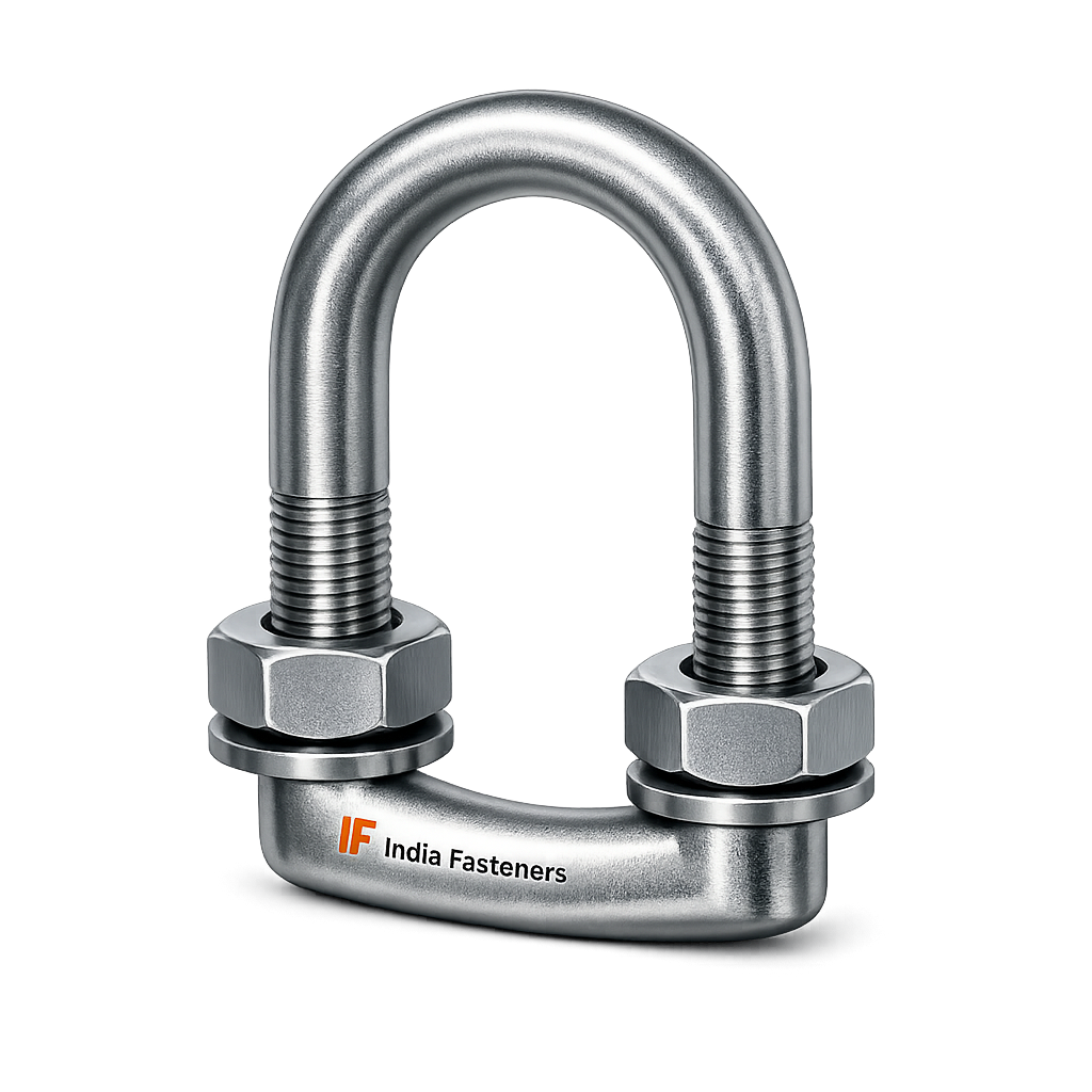
Within these support systems, U bolts function as a primary pipe restraint and clamping element, securing circular piping to structural supports such as steel channels, I-beams, support frames, or pipe racks.
For EPC contractors executing projects across Saudi Arabia, the United Arab Emirates, Qatar, and neighboring Gulf countries, pipe supports must comply with strict engineering practices derived from international codes and project-specific specifications.
These requirements typically reference:
- ASME piping design codes
- ASTM material specifications
- EPC contractor engineering standards
- project-specific pipeline support specifications
Pipe supports must be capable of maintaining pipe stability while accommodating thermal expansion, mechanical loads, and environmental exposure typical of desert and coastal industrial zones.
1.1 Oil & Gas Pipeline Support Systems
Oil and gas infrastructure across the GCC region involves extensive pipeline networks transporting crude oil, refined petroleum products, natural gas, and associated process fluids.
Pipelines may extend:
- between wellheads and processing facilities
- between refineries and export terminals
- between storage tanks and process units
- across cross-country transmission corridors
In above-ground pipeline sections, pipes are typically supported on steel structures at calculated intervals. U bolts secure the pipe to the support beam or channel, preventing lateral displacement and controlling vibration.
Typical design considerations include:
- pipe weight under full operating conditions
- fluid density and internal pressure
- thermal expansion due to temperature variation
- wind load for exposed pipelines
- vibration from pumping equipment
In such installations, the U bolt acts as the primary mechanical restraint element preventing pipe movement while maintaining controlled flexibility in the support system.
1.2 Petrochemical Plant Pipe Racks
Large petrochemical facilities contain extensive pipe rack structures supporting hundreds of process pipelines running across production units.
Pipe racks often carry multiple piping systems including:
- hydrocarbon process lines
- cooling water circuits
- steam pipelines
- instrument air lines
- chemical transfer pipelines
In these environments, pipe supports must manage significant operational loads while maintaining accurate pipe alignment.
U bolts are commonly used together with:
- pipe support plates
- saddle clamps
- structural channels
- guide assemblies
Pipe racks experience significant thermal expansion due to process temperature variations. The support system must therefore allow controlled sliding movement where required, while maintaining vertical restraint.
U bolts are frequently used in:
- guide supports
- anchor supports
- resting supports with clamp plates
Proper sizing and installation of the U bolt ensures the pipe remains correctly positioned without introducing excessive localized stress.
1.3 Refinery Piping Corridors
Refinery processing units contain densely arranged piping corridors where pipe supports must maintain precise alignment while accommodating equipment-induced vibration.
Typical refinery piping systems include:
- crude oil distillation units
- catalytic cracking systems
- hydrotreating units
- sulfur recovery systems
These process environments involve high temperatures and pressure fluctuations.
Pipe supports within these areas must maintain mechanical integrity despite:
- cyclic thermal expansion
- vibration from compressors and pumps
- chemical exposure
- occasional mechanical shock loads during plant operation
U bolts used in refinery pipe supports must therefore be manufactured from materials capable of maintaining strength and dimensional stability under such conditions.
1.4 LNG Terminal Pipelines
Liquefied natural gas facilities present unique pipeline support requirements due to extremely low operating temperatures in cryogenic systems combined with high-temperature process equipment elsewhere in the facility.
Typical LNG terminal piping includes:
- cryogenic LNG transfer pipelines
- regasification lines
- process gas piping
- utility pipelines
Pipe supports must accommodate large temperature gradients across the facility.
U bolts used in such environments must be manufactured using materials suitable for the expected service temperature range. Material selection is therefore critical to ensure mechanical performance without brittle fracture risk at low temperatures.
1.5 Desalination Plant Pipelines
The Middle East relies heavily on desalination plants to supply potable water to urban populations. These plants operate extensive piping networks for seawater intake, treatment, and freshwater distribution.
Piping systems typically include:
- seawater intake pipelines
- brine discharge pipelines
- process piping within treatment systems
- freshwater distribution pipelines
Many of these pipelines are located in highly corrosive marine environments.
Pipe support systems used in desalination plants must therefore consider corrosion protection and long-term durability.
U bolts installed in these systems are frequently produced using:
- hot-dip galvanized carbon steel
- stainless steel materials
- corrosion-resistant coatings
Proper material selection prevents premature degradation caused by salt exposure and coastal humidity.
1.6 Power Plant Steam Piping
Thermal power plants operating in the Gulf region rely on extensive high-temperature steam piping networks connecting boilers, turbines, and auxiliary systems.
Steam pipelines often operate at temperatures exceeding several hundred degrees Celsius. Pipe supports must therefore manage:
- high thermal expansion forces
- pipe weight at elevated temperatures
- dynamic loading during plant startup and shutdown
U bolts used in steam piping support systems must maintain their mechanical integrity under elevated temperature conditions.
Material selection for these applications typically involves high-strength alloy steels designed for high-temperature service.
1.7 District Cooling Infrastructure
District cooling networks are widely used across the Middle East to provide centralized chilled water distribution to commercial buildings, residential developments, and industrial facilities.
These systems involve extensive piping networks transporting chilled water through underground and above-ground piping corridors.
Typical conditions include:
- continuous operation
- large pipe diameters
- exposure to outdoor environmental conditions
Pipe support systems must maintain pipe alignment and prevent mechanical stress accumulation within the distribution network.
U bolts serve as a primary pipe clamping mechanism within these support assemblies.
1.8 Offshore Platform Pipe Supports
Offshore oil and gas facilities operate in one of the most demanding structural environments due to constant exposure to marine conditions.
Pipelines installed on offshore platforms must withstand:
- saltwater corrosion
- continuous vibration from equipment
- structural movement due to wave loading
Pipe support assemblies used offshore must therefore provide secure restraint while resisting corrosion.
U bolts used in offshore piping systems are frequently manufactured using corrosion-resistant materials such as stainless steel or protected carbon steel alloys.
2. Technical Definition of U Bolt
A U bolt is a U-shaped threaded fastener designed specifically to support cylindrical objects such as pipes and tubes.
The fastener consists of a curved rod with threaded ends that allow the pipe to be clamped securely to a structural support member.
In industrial piping systems, the U bolt functions as a pipe restraint fastener that prevents displacement of the pipe while maintaining controlled positioning relative to the supporting structure.
2.1 Basic Structural Components
A typical pipe support U bolt assembly consists of the following components:
U-Shaped Rod
The primary structural element is a steel rod bent into a symmetrical U-shape. The curvature of the rod corresponds to the outside diameter of the supported pipe.
The radius of the bend is controlled during manufacturing to ensure proper pipe fitment.
Threaded Legs
Both ends of the U-shaped rod are threaded to allow nuts and washers to be installed.
These threaded sections allow controlled tightening force to be applied during installation.
Threads may be produced by:
- thread rolling
- thread cutting
Thread rolling is typically preferred in high-strength fasteners because it preserves grain structure and improves fatigue resistance.
Nuts and Washers
Hexagonal nuts are installed on the threaded legs of the U bolt to secure the pipe clamp assembly.
Washers are typically used to:
- distribute clamping force
- protect support surfaces
- improve load distribution
In high-load installations, hardened washers may be specified.
Pipe Saddle or Clamp Plate
In many pipe support designs, a saddle plate or clamp plate is installed between the U bolt and the pipe to distribute the load more evenly across the pipe surface.
This prevents localized stress concentration on the pipe wall.
2.2 Threading Standards
U bolts used in industrial piping supports may be manufactured using either metric or imperial threading systems depending on the project specification.
Common threading standards include:
UNC (Unified National Coarse)
UNC threads are widely used in North American industrial fastener systems and appear frequently in international EPC projects.
Characteristics:
- larger thread pitch
- easier installation in field conditions
- good resistance to thread damage
UNF (Unified National Fine)
UNF threads feature a finer pitch and provide greater clamping force for the same bolt diameter.
These threads are typically used in high-precision applications.
ISO Metric Threads
Metric threads are widely used in international industrial projects and infrastructure installations.
Metric threading systems follow ISO standards and are commonly used in pipe support fasteners supplied to international EPC projects.
2.3 Pipe Outside Diameter vs Nominal Pipe Size
When selecting a U bolt for a pipe support system, it is important to distinguish between nominal pipe size (NPS) and actual pipe outside diameter (OD).
Nominal pipe size is a standardized designation used in piping systems. However, the physical outside diameter of the pipe remains constant across different pipe schedules.
For example:
- NPS 4 pipe has an outside diameter of approximately 114.3 mm
- NPS 6 pipe has an outside diameter of approximately 168.3 mm
U bolt inside width must therefore correspond to the actual outside diameter of the pipe, not the nominal pipe size designation.
Proper dimensional matching ensures the U bolt clamps the pipe securely without excessive clearance or excessive compressive stress.
3. Pipe Support Load Theory
The design of pipe support systems requires careful evaluation of mechanical loads acting on the piping network. U bolts serve as one component within the overall support structure and must therefore be selected based on engineering load calculations.
These calculations typically consider multiple load components.
3.1 Dead Load from Pipe Weight
The most fundamental load acting on a pipe support is the weight of the pipe itself.
Pipe weight depends on:
- pipe outside diameter
- wall thickness
- material density
- pipe length between supports
The basic weight calculation is expressed as:
Pipe Weight = Pipe Volume × Material Density
Where pipe volume is derived from the difference between outer and inner pipe diameters.
3.2 Fluid Weight Inside Pipeline
In most industrial pipelines, the pipe contains a fluid such as water, hydrocarbons, chemicals, or steam.
The weight of this fluid contributes to the total load applied to the pipe support system.
Fluid weight is calculated as:
Fluid Weight = Fluid Density × Internal Pipe Volume
This load must be added to the pipe self-weight when determining support design.
3.3 Thermal Expansion Forces
Pipelines exposed to temperature changes expand or contract along their length.
In desert environments typical of the Middle East, pipelines may experience significant temperature variation between daytime and nighttime conditions.
Thermal expansion of piping systems produces axial forces that must be accommodated by the support structure.
If pipe movement is restrained improperly, excessive stress may develop in the pipe wall or support components.
U bolts used in sliding supports must therefore allow controlled movement where required.
3.4 Vibration Loads
Many industrial pipelines are connected to rotating equipment such as:
- pumps
- compressors
- turbines
These machines generate vibration that propagates through the piping system.
Repeated vibration can cause fatigue loading in pipe supports and fasteners.
U bolts used in these environments must maintain clamping force while resisting fatigue failure.
Proper installation torque and washer selection help distribute vibration loads effectively.
3.5 Wind Loading for Exposed Pipelines
Pipelines installed above ground or on elevated pipe racks may be exposed to significant wind forces.
These forces act on both the pipe and the support structure.
Wind loads are typically calculated using structural engineering methods based on:
- pipe diameter
- wind speed
- pipeline elevation
These loads may introduce lateral forces that must be resisted by the pipe support system.
U bolts play a role in preventing pipe displacement under such conditions.
3.6 Pipe Weight Calculation Formula
The weight of a steel pipe section can be approximated using:
Weight per unit length =
$\frac{\pi \times \left(OD^2 – ID^2\right)}{4} \times \text{Density}$
Where:
$OD$= outside diameter
$ID$= inside diameter
Density for carbon steel is approximately 7850 kg/m³.$OD$
This calculation allows engineers to determine the load applied to each pipe support location.
3.7 Support Spacing Calculation
Pipe supports are installed at intervals determined by pipe size, material, and operating conditions.
Typical support spacing is based on deflection limits that prevent excessive pipe sag.
Support spacing is influenced by:
- pipe diameter
- pipe wall thickness
- operating temperature
- fluid density
3.9 Allowable Stress and Safety Factors
Engineering design of pipe supports includes safety factors to ensure reliable operation under varying load conditions.
Typical safety factors used in pipe support design range between:
- 2.0 to 4.0 depending on project specification
These factors account for uncertainties in:
- load estimation
- material variability
- installation conditions
- environmental exposure
The selected U bolt must therefore possess sufficient mechanical capacity to operate within these safety limits.
Material Engineering, Standards & Manufacturing Discipline for Industrial U Bolts
4. Applicable Standards Mapped to GCC Industrial Use
Industrial pipe support fasteners used in Middle East infrastructure projects must comply with internationally recognized material standards. EPC contractors and consultants typically require materials conforming to ASTM, ISO, and ASME specifications, supported by mill test certification and traceability documentation.
For U bolts used in pipeline and pipe support assemblies, material selection depends primarily on:
- operating temperature
- mechanical loading
- corrosion exposure
- project specification requirements
- inspection and certification obligations
Material grades commonly specified in GCC pipeline and industrial projects include carbon steel, alloy steel, and stainless steel fastener materials defined by ASTM standards.
4.1 ASTM A193 Alloy Steel Fastener Materials
ASTM A193 specifies alloy steel and stainless steel bolting materials intended for high-temperature and high-pressure service. These materials are widely referenced in refinery, petrochemical, and power generation installations.
ASTM A193 Grade B7
ASTM A193 B7 is one of the most widely used high-strength alloy steel materials for industrial bolting.
Material characteristics:
- quenched and tempered chromium-molybdenum alloy steel
- high tensile strength
- good fatigue resistance
- suitable for elevated temperature applications
Typical use in pipe support systems includes:
- heavy-duty pipeline U bolts
- refinery piping supports
- structural pipe restraints in process plants
For applications involving elevated operating temperatures or heavy mechanical loading, B7 material provides improved mechanical strength compared to standard carbon steel.
ASTM A193 Grade B8
ASTM A193 B8 corresponds to stainless steel fasteners manufactured from austenitic stainless steel equivalent to Type 304.
Material characteristics include:
- corrosion resistance in atmospheric environments
- good ductility and toughness
- non-magnetic properties in annealed condition
Typical applications:
- water pipelines
- desalination plant pipe supports
- outdoor infrastructure installations
ASTM A193 Grade B8M
ASTM A193 B8M corresponds to austenitic stainless steel equivalent to Type 316.
This material includes molybdenum, improving resistance to chloride-induced corrosion.
Typical applications include:
- marine environments
- offshore installations
- desalination plants
- coastal industrial facilities
Where exposure to saltwater or high humidity conditions is expected, B8M material is frequently specified for U bolt production.
4.2 ASTM A320 Low Temperature Bolting Materials
ASTM A320 covers alloy steel and stainless steel bolting materials intended for low-temperature service.
ASTM A320 Grade L7
This material grade is commonly used where piping systems may experience low operating temperatures.
Characteristics include:
- good toughness at low temperature
- resistance to brittle fracture
- quenched and tempered alloy steel
Although more common in pressure equipment bolting, L7 material may also be used in U bolts supporting cryogenic piping systems such as LNG facilities.
4.3 ASTM A307 Carbon Steel Fasteners
ASTM A307 specifies carbon steel bolts and threaded rods used in general structural applications.
Characteristics include:
- moderate mechanical strength
- cost-effective production
- suitable for non-critical structural pipe supports
ASTM A307 materials are typically used in:
- light industrial piping systems
- structural pipe supports in infrastructure projects
- mechanical installations where high strength is not required
However, in refinery or petrochemical facilities, higher-strength materials are usually preferred.
4.4 ASTM A36 Structural Steel
ASTM A36 is a structural carbon steel grade commonly used for fabrication of support structures such as:
- pipe rack beams
- structural channels
- pipe support frames
While A36 is not typically used for threaded fasteners, it may appear in U bolt production where the fastener is manufactured from structural rod material rather than specialized fastener steel.
Mechanical properties of A36 are lower than alloy steel grades and must therefore be considered carefully in load calculations.
4.5 ISO 898 Mechanical Property Standards
ISO 898 defines mechanical property classes for metric fasteners.
Common property classes include:
- Class 4.6
- Class 8.8
- Class 10.9
These classifications specify minimum mechanical performance including:
- yield strength
- tensile strength
- elongation characteristics
4.7 ASME B31.3 Piping Support Considerations
ASME B31.3 governs the design of process piping in refineries and petrochemical plants.
While the code does not directly specify U bolt design, it establishes requirements for piping support systems including:
- load analysis
- stress limits
- thermal expansion accommodation
- structural stability
U bolts used in piping supports must therefore be selected in accordance with the overall support design developed under ASME B31.3 engineering analysis.
5. Material Comparison Table
The following table summarizes mechanical and environmental characteristics of common materials used in U bolt manufacturing for industrial piping systems.
| Material Grade | Yield Strength (MPa) | Tensile Strength (MPa) | Temperature Limit | Corrosion Resistance | Typical Application |
|---|---|---|---|---|---|
| ASTM A307 Carbon Steel | ~250 | ~415 | Moderate temperature service | Low without coating | Structural pipe supports |
| ASTM A193 B7 Alloy Steel | ~720 | ~860 | High temperature capable | Moderate | Oil & gas pipeline supports |
| ASTM A320 L7 Alloy Steel | ~720 | ~860 | Low temperature service | Moderate | Cryogenic pipelines |
| ASTM A193 B8 (SS304) | ~205 | ~515 | Moderate temperature | Good atmospheric corrosion resistance | Water systems |
| ASTM A193 B8M (SS316) | ~205 | ~515 | Moderate temperature | Excellent marine corrosion resistance | Offshore / desalination |
Material selection should be based on environmental exposure, design loads, and project specification requirements.
6. Heat Treatment and Metallurgical Control
Mechanical performance of industrial fasteners depends significantly on the heat treatment processes applied during manufacturing.
Heat treatment modifies the microstructure of steel to achieve desired strength, hardness, and toughness properties.
6.1 Quenching and Tempering
Alloy steel fasteners such as ASTM A193 B7 are typically subjected to quenching and tempering.
Process steps include:
- Heating the material to the austenitizing temperature
- Rapid cooling (quenching) in oil or water
- Reheating to a lower temperature for tempering
This process produces a microstructure that combines high strength with adequate ductility.
Quenching and tempering also improve fatigue resistance in cyclic loading environments.
6.2 Normalizing
Normalizing is a heat treatment process used for certain carbon steel materials.
The material is heated above its critical temperature and allowed to cool in air.
This process:
- refines grain structure
- improves uniformity of mechanical properties
- reduces residual stresses from forming operations
Normalizing may be applied to rod materials before bending operations used to form U bolts.
6.3 Solution Annealing for Stainless Steel
Stainless steel fasteners such as ASTM A193 B8 and B8M are typically solution annealed.
Process steps include:
- Heating to approximately 1000–1100°C
- Rapid cooling
Solution annealing dissolves chromium carbides and restores corrosion resistance.
It also ensures the stainless steel retains its characteristic ductility and toughness.
6.4 Stress Relief Heat Treatment
After bending operations, certain fasteners may undergo stress relief heat treatment.
This process reduces internal stresses introduced during forming operations such as U-bending.
Stress relief helps prevent distortion during service and improves dimensional stability.
6.5 Hardness Control
Mechanical properties of alloy steel fasteners are typically verified through hardness testing.
Hardness limits are specified in ASTM standards.
For example:
ASTM A193 B7 fasteners generally fall within a hardness range of approximately 24–35 HRC.
Excessive hardness may indicate susceptibility to brittle fracture or hydrogen embrittlement.
6.6 Hydrogen Embrittlement Prevention
High-strength fasteners exposed to hydrogen during plating or pickling processes may experience hydrogen embrittlement.
Preventive measures include:
- controlled electroplating processes
- post-plating baking
- avoidance of hydrogen-producing environments during manufacturing
For critical industrial fasteners, hydrogen embrittlement control is an important manufacturing consideration.
7. Manufacturing Process Flow for U Bolts
Production of industrial U bolts requires controlled manufacturing processes to ensure dimensional accuracy, mechanical performance, and traceability.
7.1 Raw Material Procurement and Traceability
Manufacturing begins with procurement of steel rods meeting specified material grades.
Raw materials must be accompanied by:
- mill test certificates
- chemical composition data
- mechanical property verification
Batch numbers are recorded to maintain traceability throughout production.
7.2 Rod Cutting
Steel rods are cut into predetermined lengths according to the required U bolt dimensions.
Cutting methods may include:
- automated cold saw cutting
- shear cutting
- precision band sawing
Accurate length control is necessary to maintain consistent finished dimensions.
7.3 CNC Bending for U Shape Formation
The cut rods are bent using specialized bending equipment.
Modern production facilities often employ CNC-controlled bending machines to ensure consistent geometry.
Critical parameters include:
- inside width
- bend radius
- leg symmetry
- vertical alignment of threaded ends
Accurate bending ensures proper fitment with the pipe outside diameter.
7.4 Thread Rolling or Thread Cutting
Threads are produced on both legs of the U bolt.
Two common methods are used:
Thread Rolling
Thread rolling forms threads by plastically deforming the material between hardened dies.
Advantages include:
- improved fatigue resistance
- smoother thread surface
- preservation of grain structure
Thread rolling is generally preferred for high-strength fasteners.
Thread Cutting
Thread cutting removes material using cutting tools.
Although simpler to implement, this method may reduce fatigue resistance due to interruption of grain flow.
Thread cutting is often used for larger diameter fasteners or specialized thread forms.
7.5 Heat Treatment
Where required by material specification, U bolts undergo heat treatment after forming.
Typical processes include:
- quenching and tempering for alloy steel
- solution annealing for stainless steel
Heat treatment must be performed under controlled furnace conditions to achieve consistent metallurgical properties.
7.6 Surface Finishing
Surface protection is applied depending on service environment.
Common finishing options include:
- hot-dip galvanizing
- black oxide coating
- zinc electroplating
- PTFE coating
- passivation for stainless steel
Surface treatment improves corrosion resistance and extends service life in harsh environments.
7.7 Dimensional Inspection
Dimensional verification is performed to ensure compliance with engineering drawings and pipe support specifications.
Inspection typically includes measurement of:
- inside width
- overall height
- thread length
- rod diameter
- bend symmetry
Precision measuring instruments are used to verify dimensional tolerances.
7.8 Mechanical Testing
Mechanical testing may include:
- tensile testing
- hardness testing
- impact testing (where required)
Testing verifies compliance with material specification requirements.
7.9 Stamping and Batch Traceability
Finished U bolts may be stamped or tagged with identification markings.
Traceability information may include:
- heat number
- batch number
- manufacturer identification
Traceability ensures that material origin and production records can be verified during inspection or project documentation review.
Technical Data Tables, Engineering Calculations & Quality Control for Industrial U Bolts
8. U Bolt Dimensional Reference Tables
Dimensional selection of U bolts used in pipe support assemblies must correspond precisely to the outside diameter of the supported pipe. In industrial piping systems, pipe sizes are commonly designated by Nominal Pipe Size (NPS) or DN (Diameter Nominal); however, the physical fit of a U bolt depends on the actual outside diameter (OD) of the pipe.
When selecting a U bolt, the following parameters must be defined:
- Pipe outside diameter (OD)
- Rod diameter (bolt diameter)
- Inside width of the U bolt
- Thread length
- Overall height of the bolt
The inside width of the U bolt must be slightly larger than the pipe OD to allow installation clearance while ensuring proper clamping.
Typical clearance allowance:
- 2 mm – 6 mm depending on pipe diameter
8.1 Standard U Bolt Dimensional Reference
| Pipe Size (NPS) | Pipe OD (mm) | Rod Diameter (mm) | Inside Width (mm) | Thread Length (mm) | Overall Height (mm) |
|---|---|---|---|---|---|
| 1″ | 33.4 | 8 | 38 | 40 | 80 |
| 1.5″ | 48.3 | 8 | 54 | 45 | 95 |
| 2″ | 60.3 | 10 | 66 | 50 | 110 |
| 3″ | 88.9 | 10 | 96 | 55 | 140 |
| 4″ | 114.3 | 12 | 122 | 60 | 170 |
| 6″ | 168.3 | 16 | 178 | 75 | 230 |
| 8″ | 219.1 | 16 | 230 | 80 | 270 |
| 10″ | 273.0 | 20 | 285 | 90 | 320 |
| 12″ | 323.9 | 20 | 335 | 100 | 370 |
| 16″ | 406.4 | 24 | 420 | 120 | 460 |
The above dimensions represent general industrial practice. Final dimensions must be determined based on project specifications and pipe support design drawings.
8.2 Dimensional Considerations in Pipe Supports
Proper dimensional selection ensures:
- uniform load distribution around pipe circumference
- correct engagement of clamp plate or saddle plate
- adequate thread engagement for nuts and washers
If the U bolt inside width is excessively large, the pipe may experience movement during vibration or thermal expansion cycles.
If the width is too small, excessive clamping force may be applied to the pipe wall, potentially damaging pipe coatings or insulation.
9. Load Capacity Table for U Bolts
Load capacity of a U bolt depends primarily on the diameter of the rod and the material strength.
The table below provides approximate tensile load capacities for carbon steel fasteners with typical mechanical properties comparable to medium-strength alloy steels used in industrial applications.
| Bolt Size | Nominal Diameter (mm) | Tensile Stress Area (mm²) | Approx. Tensile Capacity (kN) |
|---|---|---|---|
| M10 | 10 | 58 | 40 |
| M12 | 12 | 84 | 60 |
| M16 | 16 | 157 | 110 |
| M20 | 20 | 245 | 170 |
| M24 | 24 | 353 | 250 |
| M30 | 30 | 561 | 400 |
These values represent theoretical tensile capacity under ideal conditions.
In pipe support design, the allowable working load must be reduced using appropriate safety factors.
Typical engineering practice uses safety factors between 2 and 4, depending on:
- project code requirements
- load uncertainty
- environmental exposure
- installation conditions
Therefore, the allowable working load is typically much lower than the theoretical tensile capacity.
10. Bolt Torque Chart (Installation Reference)
Proper torque application is essential to achieve correct clamping force without overstressing the fastener.
Torque requirements depend on:
- bolt diameter
- material grade
- lubrication condition
- thread friction characteristics
Typical recommended torque values for carbon steel U bolts are shown below.
| Bolt Size | Dry Torque (Nm) | Lubricated Torque (Nm) | Typical Material Grade |
|---|---|---|---|
| M10 | 45 | 32 | Carbon steel |
| M12 | 80 | 56 | Carbon steel |
| M16 | 200 | 140 | Alloy steel |
| M20 | 390 | 275 | Alloy steel |
| M24 | 675 | 475 | Alloy steel |
| M30 | 1350 | 950 | Alloy steel |
Lubricated threads require lower torque due to reduced friction between thread surfaces.
When tightening U bolts in pipe supports, installation personnel must apply torque gradually and evenly to both legs of the bolt to maintain uniform clamping pressure.
Uneven tightening may result in pipe misalignment or uneven stress distribution.
11. Pipe Support Load Calculation Guide
Selection of U bolts for pipe support assemblies must be based on engineering load calculations considering pipe weight, fluid content, and support spacing.
The following simplified example illustrates the calculation process.
11.1 Example Parameters
Pipe diameter: 168 mm (6-inch pipeline)
Pipe material: Carbon steel
Pipe wall thickness: 7 mm
Fluid type: Water
Fluid density: 1000 kg/m³
Support spacing: 6 meters
11.2 Pipe Weight Calculation
Approximate steel pipe weight:
Pipe weight per meter ≈ 28 kg/m
For a support spacing of 6 meters:
Total pipe weight:
28 × 6 = 168 kg
11.3 Fluid Weight Calculation
Internal pipe volume per meter:
π × (ID² / 4)
Internal diameter ≈ 154 mm
Volume per meter ≈ 0.0186 m³
Fluid weight per meter:
0.0186 × 1000 = 18.6 kg
Fluid weight for 6 meters:
18.6 × 6 = 112 kg
11.4 Total Supported Load
Pipe weight = 168 kg
Fluid weight = 112 kg
Total load on support:
280 kg
Converted to force:
280 kg × 9.81 ≈ 2747 N
11.5 U Bolt Selection
For this load level, even a small diameter fastener such as M12 could theoretically support the load.
However, engineering design must also consider:
- vibration
- thermal expansion
- installation tolerances
- safety factors
Therefore, larger diameter fasteners such as M16 or M20 are typically used in industrial pipe support systems.
12. Mechanical Property Table
Mechanical performance of U bolts depends on the material grade and heat treatment applied during manufacturing.
Typical mechanical properties are summarized below.
| Material Grade | Yield Strength (MPa) | Tensile Strength (MPa) | Elongation (%) | Hardness |
|---|---|---|---|---|
| ASTM A307 | 250 | 415 | 20 | ~HRB 69 |
| ASTM A193 B7 | 720 | 860 | 16 | 24–35 HRC |
| ASTM A320 L7 | 720 | 860 | 16 | 24–35 HRC |
| ASTM A193 B8 | 205 | 515 | 30 | HRB ≤95 |
| ASTM A193 B8M | 205 | 515 | 30 | HRB ≤95 |
These mechanical properties must be verified through testing in accordance with applicable ASTM standards.
13. Corrosion Resistance Comparison Table
Environmental exposure plays a significant role in selecting U bolt materials for pipeline and infrastructure installations.
The table below compares corrosion resistance characteristics of common materials used in pipe support fasteners.
| Material Type | Marine Environment | Chemical Exposure | Outdoor Pipelines | Coastal Humidity |
|---|---|---|---|---|
| Carbon Steel | Poor | Poor | Moderate with coating | Poor |
| Hot-Dip Galvanized Steel | Moderate | Limited | Good | Moderate |
| Stainless Steel 304 | Good | Moderate | Good | Good |
| Stainless Steel 316 | Excellent | Good | Excellent | Excellent |
For installations located near coastal regions in the Gulf, stainless steel or protected carbon steel materials are often selected to ensure long-term corrosion resistance.
14. Inspection and Quality Assurance
Pipe support fasteners supplied to industrial EPC projects must undergo inspection and testing procedures to verify compliance with project specifications.
Inspection may be performed by the manufacturer, third-party inspection agencies, or project representatives.
14.1 Dimensional Inspection
Dimensional inspection verifies that the U bolt geometry conforms to engineering drawings and tolerance limits.
Typical measurements include:
- rod diameter
- inside width
- thread length
- bend radius
- overall height
Precision instruments such as calipers and gauges are used to verify these dimensions.
14.2 Thread Gauge Verification
Threads must conform to applicable standards such as UNC, UNF, or ISO metric.
Thread quality is verified using:
- GO thread gauges
- NO-GO thread gauges
These gauges confirm that thread dimensions fall within acceptable tolerance limits.
14.3 Hardness Testing
Hardness testing verifies that heat treatment processes have achieved the required mechanical properties.
Common testing methods include:
- Rockwell hardness testing
- Brinell hardness testing
Hardness values must fall within limits specified by ASTM standards.
14.4 Mechanical Testing
Mechanical testing may include tensile testing to confirm material strength properties.
Test samples are typically taken from representative batches.
Mechanical testing verifies compliance with required:
- yield strength
- tensile strength
- elongation properties
14.5 Positive Material Identification (PMI)
For alloy steel and stainless steel fasteners, Positive Material Identification may be required to verify chemical composition.
PMI testing is performed using handheld spectrometers or X-ray fluorescence devices.
This procedure confirms that the material corresponds to the specified grade.
14.6 Documentation and Certification
Industrial projects in the Middle East require detailed documentation for supplied fasteners.
Typical documentation includes:
- mill test certificates
- heat number traceability records
- dimensional inspection reports
- hardness test reports
- coating inspection reports
Material certification typically follows EN 10204 documentation standards.
Common document types include:
EN 10204 3.1 certificates issued by the manufacturer.
In certain projects, third-party inspection agencies may provide 3.2 certification, verifying compliance independently.
14.7 Third-Party Inspection Expectations
Large EPC projects frequently require inspection by independent certification bodies.
Inspection agencies typically verify:
- material certification
- dimensional conformity
- mechanical testing records
- coating thickness measurements
- traceability markings
This process ensures that pipe support fasteners meet project technical specifications and international quality standards.
GCC Industry Applications, Export Capability & Procurement Engineering View
15. Industries Served – Middle East Industrial Infrastructure
Industrial U bolts are widely used in pipe restraint and pipe support assemblies across multiple infrastructure sectors in the Gulf region. These sectors rely on extensive piping networks transporting hydrocarbons, water, steam, chemicals, and process utilities. The reliability of these systems depends heavily on the integrity of pipe support structures and the fasteners used within them.
Within these support assemblies, U bolts function as the primary clamping element that secures the pipe to structural supports such as channels, beams, pipe racks, or fabricated support frames.
The following sections describe typical industrial environments in which U bolts are applied across Middle East infrastructure projects.
15.1 Oil and Gas Pipelines
Oil and gas transportation infrastructure represents one of the largest applications for pipe support fasteners in the region.
Typical installations include:
- cross-country crude oil pipelines
- natural gas transmission pipelines
- refinery feed pipelines
- product transfer pipelines between processing units
Above-ground pipeline sections are often supported using steel structures spaced at calculated intervals. These supports maintain pipeline elevation, alignment, and stability while allowing controlled thermal movement.
U bolts are used to secure the pipe to the support beam or channel while preventing lateral displacement caused by:
- vibration from pumps and compressors
- wind forces acting on elevated pipelines
- operational pressure fluctuations
Properly selected U bolts ensure that the pipeline remains restrained without introducing excessive stress concentration on the pipe wall.
15.2 Refinery Processing Facilities
Refineries contain dense networks of process piping operating under varying pressure and temperature conditions.
Typical refinery piping includes:
- hydrocarbon processing lines
- high-temperature furnace piping
- cooling water circuits
- chemical injection systems
Pipe supports within refinery pipe racks must accommodate significant thermal expansion while maintaining alignment between equipment and process units.
U bolts are frequently used within support assemblies that include:
- pipe clamps
- guide supports
- resting supports
- restraint supports
The fastener must maintain structural integrity under continuous exposure to vibration, thermal cycling, and chemical environments.
15.3 Petrochemical Complexes
Petrochemical plants operate extensive piping networks connecting reactors, distillation units, and storage systems.
Typical services include:
- polymer feed lines
- chemical transfer pipelines
- solvent distribution networks
- compressed gas pipelines
Pipe support assemblies must maintain dimensional stability across large plant areas while accommodating thermal expansion in high-temperature process lines.
U bolts used in these facilities are typically manufactured using alloy steel or stainless steel materials depending on the service environment.
15.4 Power Generation Plants
Thermal power plants rely on high-pressure steam piping systems connecting boilers, turbines, and auxiliary equipment.
These pipelines operate under conditions involving:
- high temperatures
- cyclic loading during plant startup and shutdown
- vibration from rotating machinery
Pipe supports must maintain structural stability while accommodating thermal expansion of steam pipelines.
U bolts used in these supports must therefore be selected based on:
- mechanical load capacity
- high-temperature material performance
- compatibility with support hardware
15.5 Desalination Plants
Water desalination facilities form a critical component of infrastructure across the Gulf region.
These plants operate extensive piping networks for:
- seawater intake
- brine discharge
- treated water distribution
- chemical dosing systems
Many of these pipelines operate in environments exposed to saltwater, humidity, and coastal atmospheric conditions.
Pipe support fasteners used in desalination plants must therefore exhibit corrosion resistance. Materials frequently used in such environments include stainless steel grades or hot-dip galvanized carbon steel.
15.6 District Cooling Networks
District cooling infrastructure distributes chilled water from centralized plants to commercial and residential developments.
These networks involve large-diameter pipelines installed above ground, underground, or within utility corridors.
Pipe supports must maintain alignment of chilled water pipelines while accommodating:
- thermal contraction at low operating temperatures
- expansion during system shutdown
- vibration from circulation pumps
U bolts serve as the primary clamping component within pipe support assemblies used in district cooling infrastructure.
15.7 Industrial Pipe Racks
Industrial facilities frequently use pipe rack structures to carry multiple pipelines across plant areas.
These pipe racks may support:
- hydrocarbon process lines
- cooling water pipelines
- compressed air systems
- fire protection water lines
Pipe supports installed on these racks must maintain spacing between pipelines while ensuring structural stability.
U bolts used in pipe rack supports must maintain dimensional accuracy to ensure uniform load distribution and proper pipe positioning.
15.8 Infrastructure and Utility Projects
Beyond oil and gas facilities, U bolts are also used in general infrastructure installations including:
- water transmission pipelines
- wastewater treatment plants
- industrial utility corridors
- municipal infrastructure projects
In these environments, pipe supports must maintain mechanical stability while accommodating environmental exposure and operational loads.
16. Export and GCC Supply Capability
Industrial projects in the Gulf region typically involve procurement of pipe support fasteners through EPC contractors, engineering consultants, and project procurement departments.
Manufacturers supplying U bolts to such projects must maintain the ability to deliver both physical product and supporting documentation required during project qualification and inspection.
16.1 Supply to Saudi Arabia
Large-scale industrial developments in Saudi Arabia include:
- oil and gas processing facilities
- refinery expansions
- petrochemical complexes
- cross-country pipeline systems
- desalination infrastructure
Supply to these projects requires compliance with project technical specifications, including documented material traceability and inspection readiness.
16.2 Supply to United Arab Emirates
Industrial and infrastructure projects across the United Arab Emirates include:
- refinery upgrades
- offshore oil and gas developments
- district cooling systems
- power generation facilities
- water infrastructure projects
Procurement departments typically require documentation packages demonstrating material compliance and quality control procedures.
16.3 Supply to Qatar
Qatar’s industrial infrastructure includes LNG facilities, petrochemical plants, and water infrastructure.
Pipe support fasteners supplied to these projects must meet engineering specifications defined by EPC contractors and project consultants.
Material certification and dimensional verification documentation are generally required prior to shipment.
16.4 Supply to Oman, Kuwait, and Bahrain
Industrial projects across other Gulf countries include refinery operations, petrochemical plants, and infrastructure developments.
Manufacturers exporting U bolts to these regions must ensure compliance with international standards and maintain traceable production records.
16.5 Export Packaging Requirements
Fasteners exported for industrial projects must be packaged to prevent damage and corrosion during transport.
Typical export packaging practices include:
- heavy-duty wooden crates
- palletized packaging with shrink wrapping
- moisture protection materials
- corrosion inhibitor applications where required
Proper packaging prevents thread damage and protects surface coatings during international shipment.
16.6 Container Loading Practices
Industrial fasteners are typically shipped using containerized cargo.
Proper loading practices include:
- pallet stabilization
- weight distribution within container limits
- moisture protection measures
- secure crate positioning to prevent movement
These measures ensure that fasteners arrive at project sites without dimensional damage or coating deterioration.
16.7 Project Documentation Packages
Export shipments supplied to industrial EPC projects typically include technical documentation such as:
- mill test certificates
- dimensional inspection reports
- mechanical test reports
- coating inspection documentation
- packing lists and traceability records
These documents support project quality assurance requirements and allow verification by project engineers or inspectors.
17. Procurement and Installation Engineering View
Engineering teams responsible for pipe support installation must ensure that U bolts are installed in accordance with project design drawings and installation procedures.
Improper installation can lead to pipe misalignment, coating damage, or insufficient load distribution.
17.1 Pipe Alignment Verification
Before installing U bolts, the pipe must be positioned correctly within the support assembly.
Alignment verification ensures that:
- pipe elevation matches design drawings
- pipe centerline is correctly positioned
- support hardware is properly aligned
Improper alignment may result in uneven clamping forces and stress concentration.
17.2 Support Spacing Discipline
Pipe supports must be installed at intervals determined during piping stress analysis.
Incorrect support spacing can result in:
- excessive pipe deflection
- increased load on individual supports
- vibration issues
Installation teams must therefore follow the support layout defined in piping design documentation.
17.3 Torque Tightening Sequence
When tightening U bolts, nuts should be tightened gradually and evenly.
Typical procedure:
- Position U bolt around pipe and support plate
- Install washers and nuts on both threaded legs
- Apply light tightening to both sides
- Alternate tightening between legs to achieve uniform clamping force
- Apply final torque according to torque chart
This procedure prevents uneven clamping pressure.
17.4 Washer and Nut Selection
Proper selection of washers and nuts contributes to load distribution and fastener durability.
Common practice includes:
- hex nuts conforming to ASTM fastener standards
- hardened washers where high clamping force is required
Washers distribute the load over a larger surface area and reduce the risk of deformation of support plates.
17.5 Protection of Pipe Coatings
Many pipelines include protective coatings such as:
- fusion bonded epoxy
- polyethylene coatings
- insulation layers
During installation, care must be taken to avoid damage to these coatings.
Where required, protective liners or saddle plates may be installed between the U bolt and pipe surface.
17.6 Installation Inspection Checklist
Typical inspection checks during installation include:
- verification of correct bolt size
- confirmation of thread engagement
- torque verification
- inspection of pipe alignment
- confirmation of coating protection
These checks ensure the support assembly performs as intended.
17.7 Storage Requirements in Gulf Climate
Fasteners stored at project sites must be protected from environmental exposure.
Recommended storage practices include:
- covered storage areas
- protection from sand and dust
- moisture control to prevent corrosion
- separation of different material grades to maintain traceability
These precautions help maintain fastener quality before installation.
18. Custom Engineering Capabilities
Industrial pipe support systems often require U bolts with dimensions and material characteristics tailored to specific project requirements.
Manufacturers supplying EPC projects must therefore maintain the ability to produce custom-engineered fasteners.
18.1 Heavy-Duty Pipeline U Bolts
Large-diameter pipelines require heavy-duty U bolts with increased rod diameters and greater mechanical load capacity.
These fasteners are typically used in:
- large transmission pipelines
- refinery piping systems
- heavy process pipelines
Design considerations include bending radius control and thread strength.
18.2 Large Diameter Pipe Supports
Pipelines used in infrastructure and industrial facilities may exceed 500 mm in diameter.
U bolts designed for such pipes require specialized forming equipment and careful dimensional control to maintain symmetry.
18.3 Custom Inside Width and Height
Pipe support designs may require specific dimensions depending on:
- pipe insulation thickness
- support plate configuration
- pipe rack geometry
Custom manufacturing allows U bolts to be produced according to engineering drawings.
18.4 Extended Thread Length
Certain installations require additional thread length to accommodate:
- thicker support plates
- multiple washers
- double nut locking systems
Extended threads allow installation flexibility.
18.5 High-Strength Alloy Steel U Bolts
For heavy industrial applications, U bolts may be produced using high-strength alloy steel materials.
These fasteners provide improved mechanical capacity for applications involving higher structural loads.
18.6 Hot-Dip Galvanized U Bolts
Where corrosion resistance is required for outdoor installations, U bolts may be hot-dip galvanized.
This coating provides a protective zinc layer that reduces corrosion in humid or coastal environments.
18.7 PTFE-Coated U Bolts
Certain chemical environments require additional corrosion protection.
PTFE coatings provide a barrier layer that improves resistance to chemical exposure and reduces friction between pipe and support components.
Conclusion
U bolts serve as a fundamental component within pipe support systems used across industrial infrastructure projects. Their performance influences the structural stability of piping networks operating in demanding environments such as refineries, petrochemical plants, power generation facilities, desalination plants, and pipeline installations.
Selection of appropriate U bolts requires careful evaluation of:
- pipe dimensions
- mechanical loads
- environmental exposure
- material properties
- applicable international standards
Manufacturers supplying industrial fasteners to Middle East infrastructure projects must maintain strict control over material selection, manufacturing processes, dimensional accuracy, and quality assurance documentation.
When these requirements are met, U bolts function reliably as structural pipe restraint components within complex piping systems operating under varying thermal and mechanical conditions.